
Overview
DST dry-running rotary vane vacuum pumps are reliable industrial vacuum pumps used for CNC vacuum clamping, handling systems, packaging, plastics and general automation. They do not use oil inside the compression chamber. Instead, they use self-lubricating carbon vanes, also called sliders, inside a rotor.
Most service issues are caused by contamination, restricted vane movement, blocked filters, incorrect installation or insufficient protection from liquid and dust. A pump that becomes hot and then stops is often not suffering from a manufacturing defect. In many cases, the motor protection switch is reacting to excessive current caused by mechanical resistance inside the pump chamber.
How a DST Dry-Running Vane Pump Works
Inside the pump, an eccentrically mounted rotor spins within a cylindrical housing. Carbon vanes slide in and out of slots in the rotor. As the rotor turns, the vanes maintain contact with the cylinder wall and create changing chamber volumes. This draws air into the inlet, compresses it and discharges it through the exhaust.
For correct operation, the vanes must move freely in their rotor slots and the cylinder wall must remain clean and smooth. If dust, liquid, resin, coolant, adhesive particles or other debris enters the pump, the vanes may stick. This creates internal drag and can overload the motor.
Common Fault: Pump Runs Briefly, Gets Hot, Then Stops
A common issue is where the pump starts normally, runs for several minutes, becomes very hot and then stops after the motor protection switch trips. This often points to internal resistance rather than an electrical motor fault.
Typical causes include:
- A separator has become full and has allowed liquid or debris to pass through.
- Dust, swarf, paper fibres, coolant mist or cutting residue has been sucked into the pump.
- The inlet filter is missing, blocked or incorrectly maintained.
- The carbon vanes are sticking inside the rotor slots.
- The cylinder wall is contaminated or scored.
Image and Video Inspection Reference
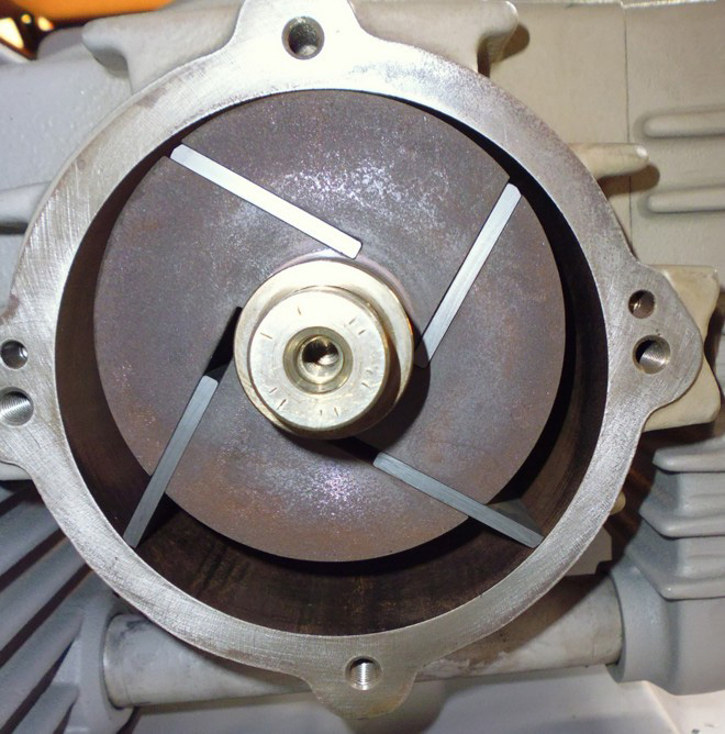
The image below shows the pump after the cover has been removed. It is useful for explaining the position of the rotor, carbon vanes and cylinder wall during inspection. The video should be used to demonstrate how the vanes should move and how smoothly the rotor should turn when the pump is clean and serviceable.
Common Symptoms and Likely Causes
| Symptom | Likely Cause | Recommended Check |
|---|---|---|
| Pump overheats and stops | Internal drag, contamination, blocked airflow or overloaded motor | Open pump and check vane movement, filters and separator |
| Motor protection switch trips | Excessive current draw caused by resistance | Check free rotation by hand and verify supply voltage |
| Reduced vacuum level | Worn vanes, air leak, blocked filter or damaged cylinder | Inspect vanes, hoses, seals and filter |
| Pump is noisy | Damaged vanes, debris inside pump or bearing wear | Inspect internal chamber and vane condition |
| Rotor difficult to turn by hand | Sticking vanes, contamination or mechanical damage | Do not restart; clean and inspect immediately |
| Excessive carbon dust | Normal vane wear or accelerated wear from contamination | Check vane length/thickness and replace if worn |
Internal Inspection Procedure
1. Isolate the pump
- Disconnect electrical power completely.
- Allow the pump to cool before opening.
- Disconnect the vacuum line where required.
- Use suitable gloves and eye protection.
2. Remove the cover
Remove the relevant pump cover carefully. Avoid damaging the gasket or sealing face. Once open, inspect the rotor, cylinder wall and carbon vanes.
3. Check the vanes/sliders
The vanes should slide freely in and out of the rotor slots. They should not be stuck, swollen, chipped, cracked or heavily worn.
4. Check the cylinder wall
The cylinder wall should be smooth. Minor polishing marks are normal, but deep scoring, grooves, burnt areas or heavy contamination indicate a problem.
5. Rotate by hand
Before restarting the pump, rotate it manually. It should move smoothly without excessive resistance or hard spots.
Internal Rotary Vane Pump Diagram
This simplified diagram shows the main internal components and airflow principle of a dry-running rotary vane vacuum pump.
Cleaning Procedure
- Remove the carbon vanes carefully and keep them in order for inspection.
- Clean the rotor slots thoroughly so each vane can move freely.
- Remove dust, residue and debris from the cylinder housing.
- Inspect the cylinder wall for scoring, grooves or heat marks.
- Check each vane for cracks, chips, swelling or excessive wear.
- Reinstall serviceable vanes or replace damaged vanes as a complete set.
- Rotate the pump manually before reconnecting power.
Electrical and Installation Checks
Three-phase pumps
For three-phase DST pumps, verify the correct rotation direction after installation. Incorrect phase rotation can reduce vacuum performance, increase heat and cause abnormal operation. If rotation is incorrect, swap any two phases.
Single-phase pumps
For single-phase pumps, check that the supply voltage matches the motor plate and that any extension cable is correctly rated. Undersized cables can cause voltage drop and overheating.
Ventilation
Ensure the pump has adequate airflow around the motor and cooling surfaces. Do not enclose the pump in a poorly ventilated cabinet without cooling provision.
Preventative Maintenance
Most DST pump failures can be prevented by maintaining clean dry airflow into the pump and protecting it from liquids, dust and machining debris.
| Maintenance Item | Recommended Interval |
|---|---|
| Check inlet filters | Weekly or more often in dusty environments |
| Empty separator | As required; never allow it to overfill |
| Check hoses and fittings | Monthly |
| Inspect vanes | Every 1,000–2,000 operating hours or when performance drops |
| Internal inspection | Annually, or immediately after contamination/liquid ingress |
Conclusion
A DST pump that overheats and stops should be inspected for internal resistance before being treated as a motor failure. Cleaning the cylinder, freeing the vanes and replacing damaged sliders will often restore correct operation. Good filtration and separator maintenance are essential for long pump life.