Vacuum clamping Vs Mechanical

Whatever you are machining, creating a firm hold on your part is essential to milling with flexibility and precision. Vacuum and mechanical clamping are two of the most common methods used each with their own advantages and disadvantages.
Vacuum Clamping
Vacuum clamping works on the principal of changing atmospheric pressure (the pressure within the atmosphere of earth) across a surface and placing your workpiece on top. With enough air pressure, below atmospheric, a workpiece can be firmly held in place.
The most common vacuum clamping method using a vacuum table with a surface in either a grid (raster) or hole grid (matrix) layout.
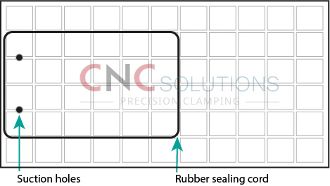
Grid vacuum tables are a cost-effective and economical solution with their air generator requirement, only needing an output of 80% to 90% which can be achieved using an inexpensive Venturi (with compressor) or domestic vacuum cleaner. The use of rubber cord into the grid grooves form a sufficient seal. And with the workpiece placed directly on the table surface a high accuracy of milling can be achieved.
Break-through milling (cutting all the way through) of small workpieces is possible by placing a PVC mat on the table surface and underneath the workpiece and cutting holes smaller than the workpiece. For example, a round part with a diameter of 100 mm needs a diameter cut of 90 mm into the PVC mat.
Once setup your workpieces can be milled without any need for additional working afterwards and is a good option for batch production of a series of small parts. However, due to the cutting and reuse of the PVC mat the setup procedure can be lengthy especially if your workpieces differ.
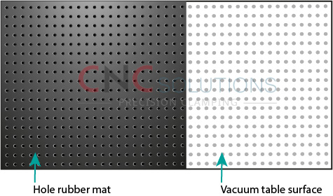
Hole grid tables overcome this with a matrix of drilled holes across the table surface. A hole rubber mat is placed onto the table surface and your workpiece on top. Making the task of break-through milling in batch and differentiating workpieces possible all in one procedure. With the hole rubber mat acting as a sacrificial material between the table surface and your workpiece.
Any possible air leakage across the table surface must be covered. On lower priced vacuum tables this can be anywhere outside of where your workpiece is placed. More sophisticated tables are constructed with vacuum chambers allowing you to zone the area on the table surface where you will be working.
However, to maintain enough clamping force a vacuum generator with a high differential pressure is necessary. Working with porous or semi-porous materials, such as wood, requires a higher demand of volume and performance from the vacuum pump.
The disadvantage to vacuum clamping is the potential loss of pressure to hold a workpiece in place and especially with break-through production. Whilst grid and hole grid vacuum tables independently try to solve these issues, with their own advantages and disadvantages, the use of vacuum clamping and using a vacuum table is a cost effective and flexible solution for precision machining.
Mechanical Clamping
Also known as top clamping is typically achieved by pushing downwards on the top of the workpiece. Unlike vacuum clamping there is no risk to loss of vacuum or clamping force. With forces applied easily tuned to a particular procedure. However enough clamping force must be sustained to allow milling on the workpiece top or sides otherwise damage will occur.
Tooling setup can be time consuming and difficult with a finished procedure requiring disassembling, to remove the completed workpieces, and setup again for the next. Mechanical clamping is certainly not as flexible or robust as vacuum clamping but used correctly and when producing certain parts it can be just as effective.